
Drone motor stator design requires balancing slot opening width, tooth width, and slot area. These dimensions affect winding feasibility, magnetic flux distribution, and copper wire arrangement, respectively.
A narrow slot opening can make winding more difficult. Insufficient tooth width may cause magnetic saturation, while a small slot area may limit the copper cross-sectional area.
The key to effective design is not maximizing or minimizing any single dimension. Instead, designers must balance electromagnetic performance, winding space, and manufacturing feasibility.
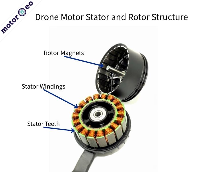
Three Key Dimensions in Drone Motor Stator Design
Take a common 12-slot, 14-pole (12N14P) outrunner drone motor as an example.
Its stator has 12 teeth with slots between them. Copper wire winds around the teeth, while magnetic flux travels through the teeth and yoke to form a magnetic circuit.
The three key dimensions are:
- Slot Opening Width: The opening between adjacent tooth tips. It affects the winding process and the air-gap magnetic field.
- Tooth Width: The width of a stator tooth. It affects magnetic flux density and the risk of magnetic saturation.
- Slot Area: The cross-sectional area between adjacent teeth that accommodates the windings. It affects copper wire arrangement and winding resistance.
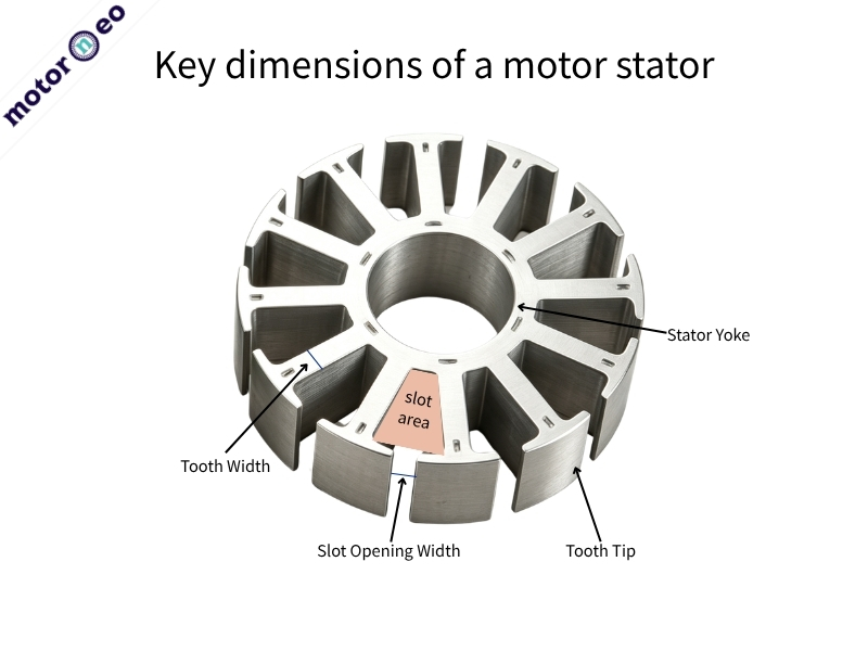
When the stator’s outer diameter, inner diameter, and slot count remain fixed, changing one dimension often affects the other two.
Slot Opening: Winding vs. Cogging Torque
The slot opening lies between adjacent stator tooth tips and faces the rotor magnets.
Can Narrow Slots Make Winding Difficult?
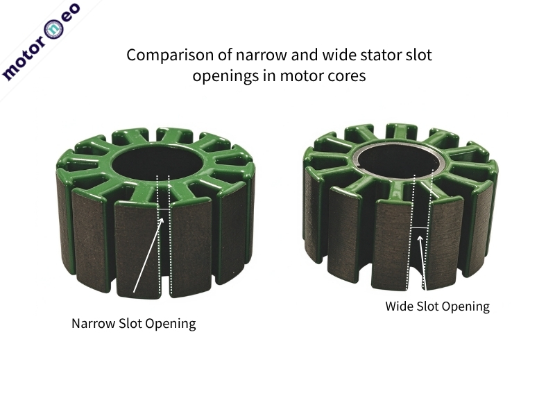
A narrower slot opening can reduce certain variations in air-gap permeance.
However, if wires or winding tools must pass through the opening, an excessively narrow slot can make winding difficult.
It may also increase the risk of damaging the enamel insulation on the wires.
Do Wider Slots Affect Cogging Torque?
Widening the slot opening can make certain winding processes easier, but it also changes the air-gap magnetic field distribution and cogging torque.
Cogging torque results from the interaction between rotor magnets and stator teeth and slots. It can affect smooth motor operation at low speeds.
However, slot opening width and cogging torque do not have a simple proportional relationship. Slot-pole combinations, magnet dimensions, and tooth tip geometry also influence cogging torque.
Therefore, designers should first consider the winding process before selecting the slot opening width. They should then use simulations to evaluate changes in the magnetic field and torque.
Tooth Width: Why Do Narrow Teeth Saturate?
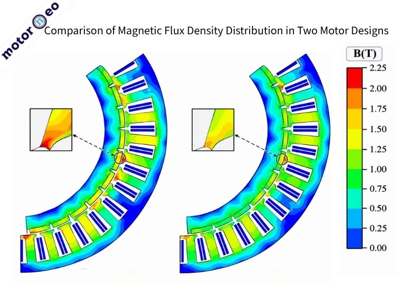
How Does Tooth Width Affect Flux Density?
Stator teeth act like channels that carry magnetic flux. When magnetic flux remains constant, reducing the tooth cross-sectional area generally increases magnetic flux density.
If the tooth width is too narrow, local magnetic saturation may occur. In this case, increasing current may not produce a proportional increase in torque. It may also cause additional losses and temperature rise.
Is Wider Always Better?
Take a drone motor with a fixed stator outer diameter as an example. Increasing the tooth width from 2.0 mm to 2.4 mm may increase the cross-sectional area available for magnetic flux. However, it may also reduce the available space in adjacent slots.
These dimensions only illustrate geometric changes and are not recommended design values.
For example, designers may widen stator teeth to reduce local magnetic flux density in a drone motor with fixed dimensions. However, they must check whether the slots can still accommodate the specified wire diameter and number of turns. Otherwise, the magnetic circuit may improve, but winding could become more difficult.
Slot Area: Why Might Wires Still Not Fit?
How to Calculate Copper Fill Factor
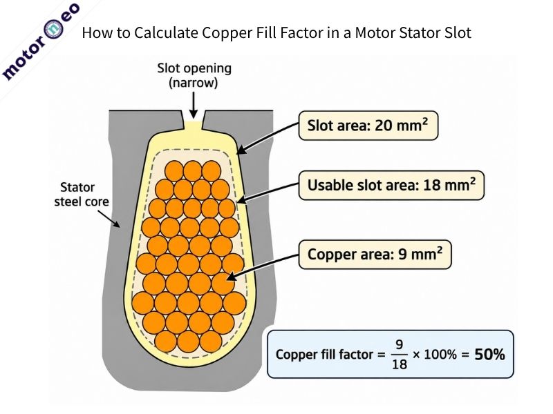
Slot area determines the geometric space available for windings. However, insulation materials and wire arrangement further reduce the usable area.
For example, a stator slot has a geometric area of 20 mm². After accounting for slot insulation and other space requirements, the usable area is 18 mm².
If the total bare copper cross-sectional area is 9 mm², the copper fill factor based on the usable area is:
Copper Fill Factor = 9 ÷ 18 × 100% = 50%
This is an illustrative calculation, not a standard copper fill factor for drone motors.
Does a Larger Slot Area Improve Efficiency?
During winding, gaps remain between round enamelled wires, and the enamel insulation also takes up space. Even if the theoretical area is sufficient, the wires may not fit properly.
With the same number of turns and conductor length, increasing the effective copper cross-sectional area generally reduces winding resistance and copper losses.
However, enlarging the slot area by reducing tooth or yoke dimensions may increase the risk of magnetic saturation.
Therefore, designers must optimize slot area together with the magnetic circuit design.
12N14P Drone Motors: Evaluating Slot Geometry
In drone motor stator design, slot opening width, tooth width, and slot area must work together. Designers should evaluate these dimensions as a whole.
Take a common 12-slot, 14-pole (12N14P) outrunner drone motor as an example. Different designs may have different slot geometries and dimensions.
For projects with existing stator drawings, we recommend checking the following three aspects:
| Inspection Item | Key Considerations |
| Slot Opening Width | Is it suitable for the selected winding method and wire diameter? |
| Tooth Width | Is the tooth flux density reasonable? Is there a risk of magnetic saturation? |
| Slot Area | Can it accommodate the required number of turns, wire diameter, and insulation materials? |
How Should Different Drone Applications Balance These Factors?
FPV motors that require fast response should prioritize torque output and dynamic performance. In contrast, industrial drones designed for prolonged hovering should focus on continuous efficiency and temperature rise.
If the existing slot geometry cannot meet the requirements, designers should evaluate possible changes through electromagnetic simulations, winding trials, and prototype testing.
They should not modify the slot opening width or tooth width without proper evaluation.
From Slot Design to Manufacturing
Passing electromagnetic simulations does not necessarily mean the design is ready for manufacturing.
What to Check Before Stamping?
First, designers should check the minimum dimensions of the slot opening and tooth tips. Thin tooth tips may make stamping more difficult. Manufacturing feasibility depends on material thickness, die design, and tolerance requirements.
Next, they should inspect the lamination edge quality. Burrs from stamping or cutting may affect how well the laminations fit together.
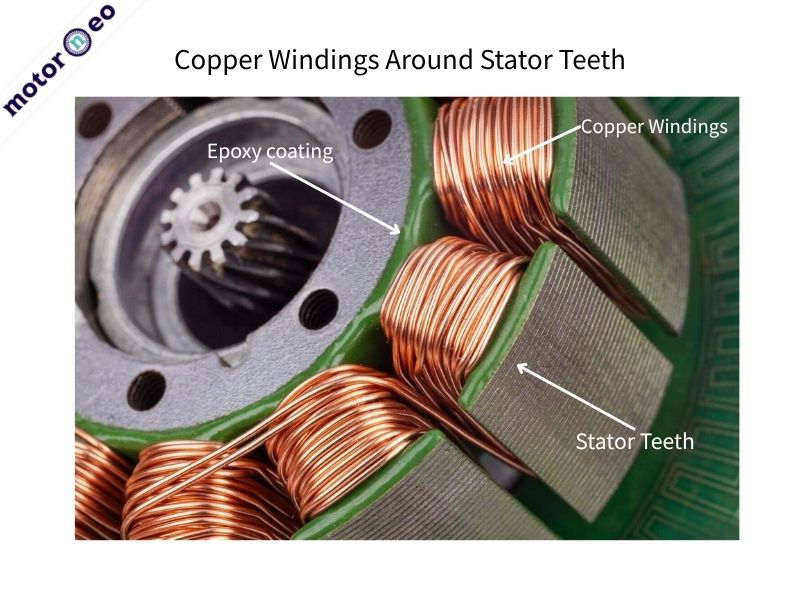
Sharp edges or burrs along the slots may also damage the enamel insulation during winding. Therefore, edge quality around the slot openings and tooth tips is equally important.
How Do Insulation and Winding Affect Design?
Designers should confirm stack height tolerances, insulation thickness, and winding methods. For stators with high copper fill factors, they must also consider coating thickness and winding space before finalizing the stamping die.
Slot opening width affects winding and the air-gap magnetic field. Tooth width influences magnetic saturation, while slot area affects copper arrangement and losses.
Balancing these three dimensions is essential for motor performance and manufacturability.
Motorneo can help evaluate slot geometry, lamination tolerances, and manufacturing feasibility based on your stator drawings.
if winding space is limited, would you adjust the slot opening, tooth width, or overall slot geometry first?**