
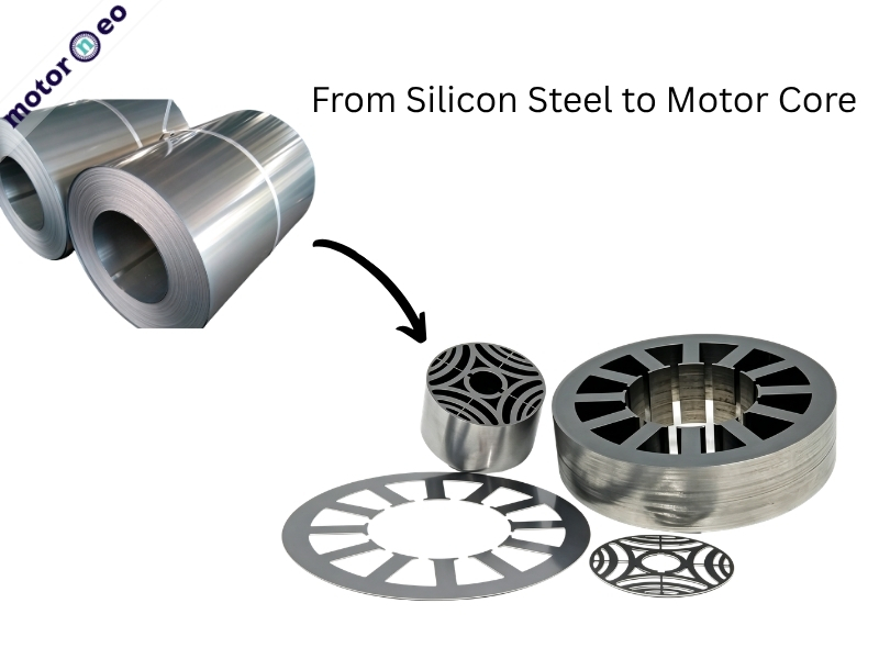
The motor core manufacturing process starts with thin silicon steel laminations, not a solid block of iron.
Manufacturers stack these laminations layer by layer to form the core. This article explains material selection, incoming inspection, slitting, forming, stacking, and fixing. It also compares suitable process routes for prototypes and mass production.
Why Silicon Steel Is Used for Motor Cores
The motor core manufacturing process starts with selecting suitable silicon steel.
Main Material for Motor Cores
Silicon steel, also called electrical steel. Steel mills produce silicon steel mainly from iron and silicon through rolling and heat treatment.
Silicon steel sheets are not all the same. For motor cores, the key point is whether the material is grain-oriented electrical steel or non-oriented electrical steel.
Grain-Oriented and Non-Oriented Silicon Steel
Electrical steel is usually divided into two types: non-oriented and grain-oriented. Non-oriented electrical steel has relatively uniform magnetic properties in all directions, making it more suitable for stator and rotor cores in rotating motors. Manufacturers mainly use grain-oriented electrical steel in applications with a fixed magnetic flux direction, such as transformer cores. Conventional rotating motors use it less often.
After the material type is confirmed, the sheet thickness also needs to be considered, because it directly affects core loss, processing difficulty, and lamination stacking cost.
How to Choose Silicon Steel Sheet Thickness
| Silicon Steel Sheet Thickness | Common Applications | Features |
| Around 0.20 mm | High-speed motors, high-efficiency motors, and small precision motors | Low loss, but more difficult to process and stack |
| 0.35 mm | Common medium- to high-efficiency motors | A relatively balanced option in terms of performance and cost |
| 0.50 mm | General industrial motors | Lower cost and good processability |
Material Inspection and Slitting for Motor Core Manufacturing
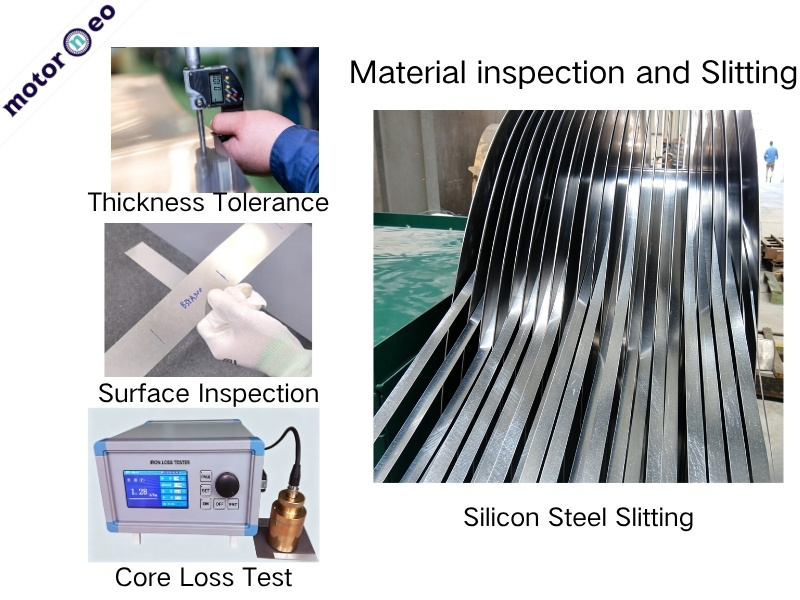
Choosing the right material does not mean production can start immediately. Before stamping or cutting, it is necessary to confirm whether the material batch is stable and process the coil into a suitable width for manufacturing.
After silicon steel coils leave the steel mill, their surfaces may develop scratches, rust, or oil stains during transportation and storage. Their thickness and magnetic properties may also vary from batch to batch. If the material is put into production without inspection, any material issue could lead to batch rework or even scrapped parts later.
This is the purpose of incoming material inspection: to keep potential problems out before production starts.
Once the material is confirmed to be qualified, the next step is to slit the wide coil into strips suitable for feeding and nesting.
Inspection Indicators
- Thickness tolerance: Whether the material meets the required standards and project specifications.
- Surface quality: Check for scratches, rust, and oil stains. Surface scratches, rust, or oil stains may affect interlaminar insulation, stamping quality, and the stability of subsequent lamination stacking.
- Core loss value: An important indicator of the material’s magnetic performance. If the core loss is too high, it may reduce motor efficiency and increase temperature rise.
Why Slitting Affects Material Utilization
Silicon steel coils supplied by steel mills are usually more than one meter wide, while the outer diameter of a motor core may be only a few dozen millimeters. The slitting width is usually determined based on the core outer diameter, nesting layout, single-row or multi-row stamping, edge allowance, and die feeding method. It is not simply equal to the outer diameter of the core.
If the slitting width is too narrow, the stamped profile may be incomplete. If it is too wide, material will be wasted. This seemingly simple process directly affects material utilization and yield in subsequent stamping.
Manufacturers usually slit conventional coil materials, including non-oriented and grain-oriented electrical steel. For amorphous, iron-cobalt, and iron-nickel alloys, they usually order narrow strips from steel mills according to the core outer diameter. Therefore, these materials generally require no further slitting after purchase.
After the strip width is determined, the next step is to actually process the silicon steel sheets into the shape of a motor core. Different project stages require different forming process routes.
Forming Methods in the Motor Core Manufacturing Process
This is the most critical step in motor core manufacturing. The choice of process depends on the project stage and precision requirements.
Prototype Stage: Laser Cutting
Laser cutting uses a high-energy beam to locally melt the sheet, while high-pressure gas blows away the molten material and cuts the profile along a preset path. The cutting path is generated directly from the CAD drawing, so no stamping die is required, and samples can usually be produced relatively quickly.
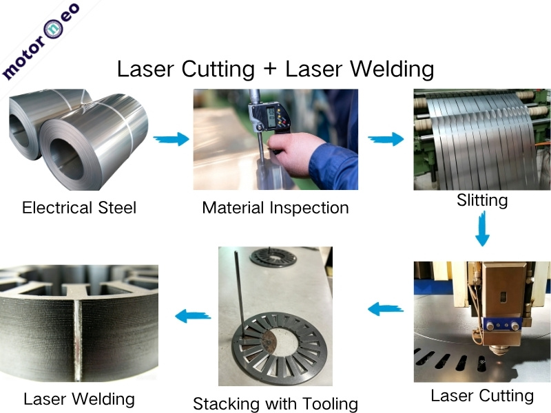
Laser cutting usually produces individual loose laminations. The process may also create heat-affected zones and burrs along the edges. Manufacturers must then stack and fix the laminations.It is more suitable for prototype validation than for long-term, low-cost mass production.
If the sample needs not only fast profile verification but also higher contour accuracy and consistency, wire EDM can be considered.
High-Precision Samples: Wire EDM
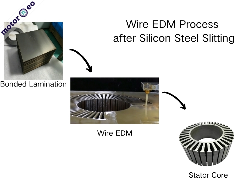
In wire EDM, a metal wire is used as the electrode. In a working fluid, electrical discharge erosion removes the material, and the profile is cut along a preset path.
According to wire travel speed, wire EDM is generally divided into fast wire, medium wire, and slow wire cutting. Slow wire cutting offers the highest precision and is suitable for high-precision samples, but it is slower and more expensive.
However, once engineers finalize the design and production volume increases, cutting becomes less economical. At this stage, manufacturers should consider stamping.
Progressive Stamping for Motor Core Mass Production
Progressive stamping uses a multi-station die on a high-speed press. The machine levels the coil and feeds it into the die. Each press stroke moves the strip to the next station. The die then completes hole punching, slot punching, outer profile blanking, and interlocking step by step.
At the final station, the die produces a complete stator or rotor lamination. If the die includes self-locking or interlocking features, it also stacks the laminations to the required core height.
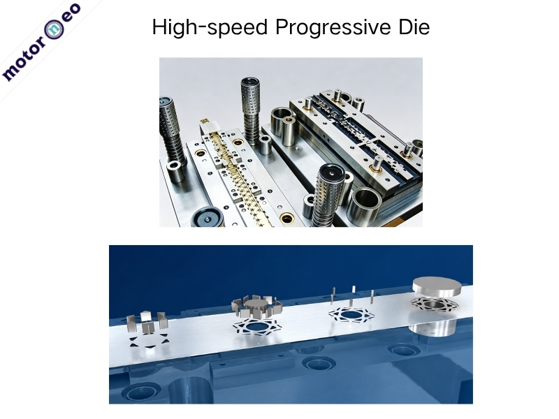
Under high-quality die conditions and stable production settings, progressive stamping can achieve accuracy at the ±0.01 mm level. High-speed stamping can reach more than 300 strokes per minute, and some equipment can run even faster. However, the actual speed, die life, and cost depend on the material thickness, core size, slot geometry complexity, and die design.
The advantage of progressive stamping is not only its speed, but more importantly its ability to maintain efficiency, dimensional consistency, and lower unit cost in long-term mass production.
In addition to progressive stamping, compound stamping and rotary stamping may also be considered for some projects with special structures or relatively low production volumes.
Compound Stamping and Rotary Stamping
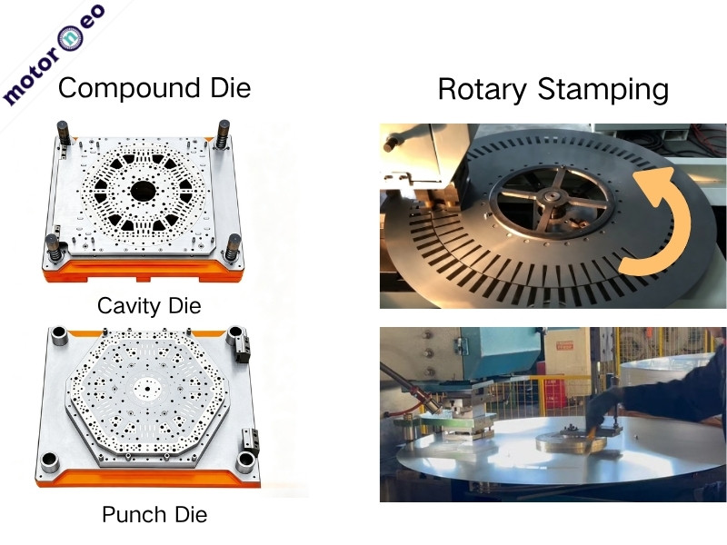
Compound stamping forms the inner hole, outer profile, and slot shape in one stroke. Unlike progressive stamping, it uses a simpler die structure. This method suits laminations with concentrated features and one-step blanking. Compound stamping can support small-batch production in the motor core manufacturing process. Its suitability depends on die cost, core size, and quantity. However, laser cutting may still suit early prototypes with frequent design changes.
Rotary stamping, also called single-slot stamping, punches one slot per stroke through indexed rotation. It runs slower than progressive stamping but requires less die investment. The slot shape is also easier to adjust. In the motor core manufacturing process, rotary stamping suits large cores, special slot designs, and non-standard projects.
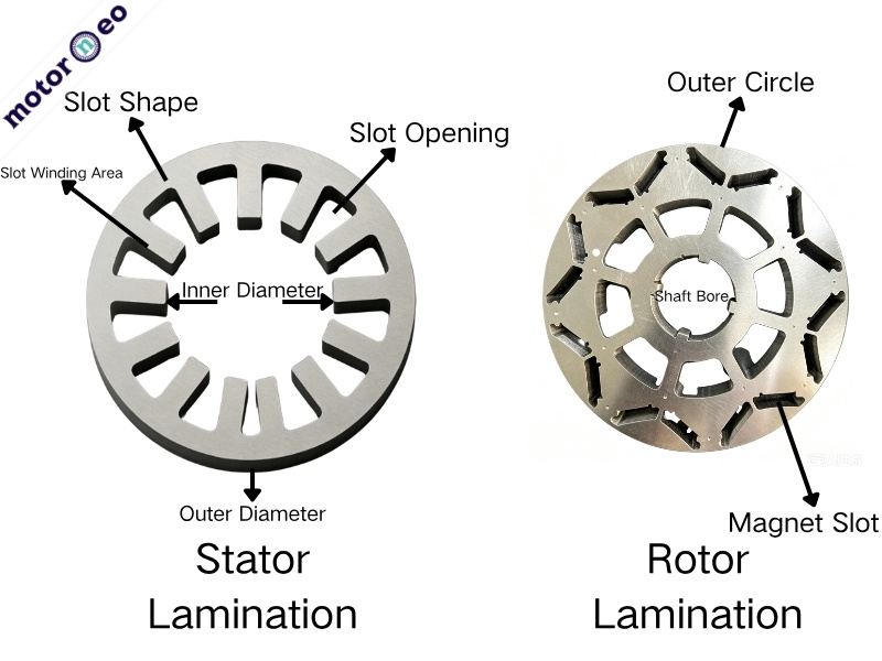
In laminations, stator laminations usually place more emphasis on slot shape, slot opening, inner and outer diameters, and the space available for subsequent winding. Rotor laminations place more emphasis on the consistency of the shaft hole, outer diameter, magnet slots, or conductor bar slots. Simply put, the stator focuses more on slot shape and assembly, while the rotor focuses more on rotational accuracy and concentricity.
Forming Route Comparison by Project Stage
When these forming methods are applied to real projects, the selection can generally be judged by the project stage. The corresponding process routes can be understood as follows:
| Project Stage | Common Processes | Selection Focus |
| Prototype Stage | Laser cutting, wire EDM | Validate the structure, make design changes easier, and avoid investing in die tooling too early. |
| Small-Batch Stage | Laser cutting, wire EDM, simple dies, single-slot stamping | Balance cost, lead time, and stability |
| Mass Production Stage | Progressive stamping | High efficiency, good consistency, and low unit cost |
For projects that require only a few dozen prototype sets, manufacturers usually choose laser cutting or wire EDM. Once the design is finalized and annual demand becomes stable, progressive stamping offers higher efficiency and a lower unit cost.
Forming only gives the silicon steel sheets the correct profile. To turn them into a motor core that can be installed in a motor, stack height, alignment, and fixing still need to be addressed.
Lamination Stacking and Fixing in Motor Core Manufacturing
Why Loose Laminations Cannot Be Used Directly
For laser cutting or loose-lamination stamping, the initial output is usually individual thin sheets. At this stage, they have not yet formed the required stack height or sufficient overall strength. They must be stacked and fixed before they can become a usable motor core.
Common Fixing Methods
- Self-locking / interlocking: High efficiency, suitable for mass production.
- Welding fixation: Good structural strength, but heat input must be controlled to avoid deformation, insulation damage, and increased local core loss.
- Adhesive bonding and curing: Good overall integrity, but glue amount, curing temperature, curing time, and heat resistance need to be controlled.
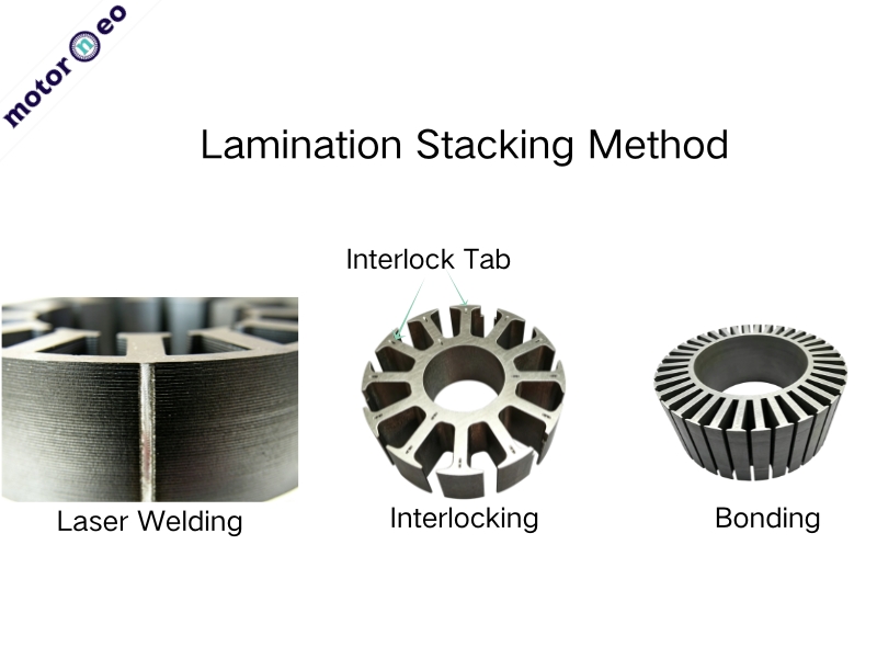
Different forming processes require different lamination stacking and fixing sequences. For laser cutting, individual laminations are usually cut first, then stacked with a fixture, and finally fixed by welding or adhesive bonding. One common method for wire EDM is to stack and bond the silicon steel sheets first, and then cut the complete core profile as a whole, which helps improve profile consistency. In progressive stamping, engineers can add locking points or interlocking features to the die. These features connect the laminations during stamping and form the motor core once the stack reaches the required height.
Quality Control in the Motor Core Manufacturing Process
Good process planning does not guarantee stable core quality. Small details often cause the biggest problems. Key controls include burrs, stack height, and slot consistency.
Burr Control
Stamping and cutting create burrs along lamination edges. Excessive burrs prevent tight stacking and create uneven end faces. They can also damage insulation coatings and weaken interlaminar insulation.
Burr control is especially important for thin laminations and high-speed motors. Inspect edge cleanliness, burr direction, and burr height, not only outer dimensions.
Stack Height
Stack height is the total height of the laminated core. It affects assembly dimensions, effective core length, and motor performance.
Actual stack height differs from sheet thickness multiplied by sheet count. Material tolerance, coating thickness, pressure, stacking factor, and fixing method all influence the result.
For 100 sheets of 0.35 mm steel, the theoretical height is 35 mm. Actual height may change with material variation, coating thickness, and compression. Control sheet count, pressing force, and stack-height tolerance together.
Slot Consistency
Slot consistency strongly affects core accuracy and assembly. Small slot deviations can accumulate through the stack.
In stators, misaligned slots hinder insulation insertion and affect winding tension and slot fill. In rotors, inaccurate magnet slots disturb magnetic symmetry. Inconsistent conductor-bar slots can reduce die-casting quality and dynamic balance.
Motor core production involves more than cutting and stacking laminations. Each project needs the right material, forming process, and quality controls. Errors in inspection, slitting, or forming can increase cost and reduce performance.
Motorneo provides custom manufacturing and processing services for stator and rotor cores. If you have a related project or sourcing requirement, please contact us to discuss your specifications.