
UAV motor efficiency can differ even when two motors use the same 0.2 mm low-loss electrical steel. Why does this happen?
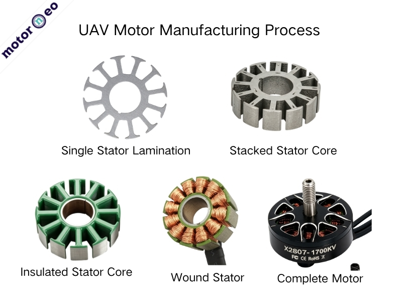
The material grade is often not the only cause. The motor does not operate with steel sheets from a datasheet. It operates with a finished stator core after punching, stacking, fixing, and assembly. Burrs, processing stress, stack-height variation, roundness, slot dimensions, and stacking methods can all reduce the material’s original performance.
For UAVs that prioritize power-to-weight ratio and flight endurance, these small errors deserve special attention.
Why Can Good Electrical Steel Lose Performance After Core Manufacturing?
A UAV stator usually consists of dozens or even hundreds of thin electrical steel laminations. Each lamination has an insulating coating to limit eddy currents. If you only check the material datasheet, you may assume low-loss steel always means a low-loss finished core.
In practice, this is not always true.
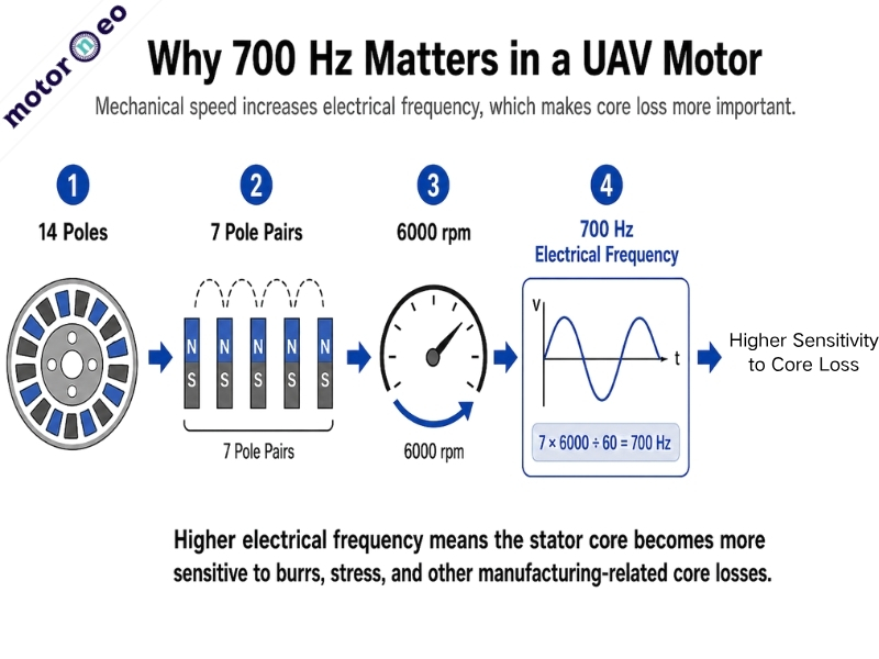
Take a common 14-pole outrunner motor as an example. Fourteen poles mean seven pole pairs. At 6000 rpm mechanical speed, the electrical frequency reaches 700 Hz.
his means the magnetic field in the stator core changes hundreds of times per second. At higher frequencies, burr-related interlaminar eddy currents and punching stress become more important. These extra core losses can increase no-load current and temperature rise, while consuming more battery energy.
So, when evaluating a UAV stator core, do not only ask, “What electrical steel grade is used?” Also ask:
How much of the material’s original magnetic performance remains after punching and stacking?
Burrs and Punching Stress
Several manufacturing factors have a direct impact on UAV motor efficiency. These include burrs, interlaminar short circuits, punching stress, and air-gap consistency. Stack height, slot dimensions, and stacking methods affect efficiency more indirectly. They mainly influence the magnetic circuit, copper loss, and product consistency.
When a lamination leaves the die, its edges cannot be perfectly smooth. Improper die clearance, worn cutting edges, or unstable punching quality can create noticeable burrs.
Why do burrs matter?
Burrs, interlaminar short circuits, punching stress, and air-gap consistency have the most direct impact on efficiency. Stack height, slot dimensions, and stacking methods affect efficiency more indirectly. They mainly influence magnetic circuits, copper loss, and product consistency.
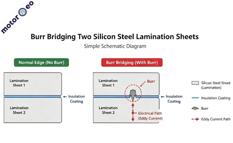
The insulating coating normally separates adjacent electrical steel laminations. Large burrs may pierce or bridge this coating during stacking. This can create local conductive paths between two or more laminations.
The result is:
Interlaminar short circuit → Additional eddy currents → Higher core loss → Local heating
For UAV motors, this problem usually does not stop the motor from running. Instead, the motor may show higher no-load current and faster temperature rise. Flight endurance may gradually decrease as a result.
Burrs are not the only factor that affects magnetic performance.
Punching also creates mechanical stress near the stator teeth and slot openings. UAV motor teeth are often narrow. Therefore, the affected area may represent a significant portion of the total tooth width.
This stress can change local magnetic properties and reduce magnetic permeability. It may also increase hysteresis loss. Narrow teeth may already operate at relatively high magnetic flux density. Reduced local magnetic performance can further worsen flux distribution and magnetic saturation.
Therefore, low-loss electrical steel alone does not guarantee high UAV motor efficiency. The finished stator core still matters.
How Stack Height, Roundness, and Slot Dimensions Affect UAV Motor Efficiency
The second type of issue comes from geometric accuracy.
For example, a stator uses 0.2 mm laminations and has a target stack height of 15 mm. In theory, it needs about 75 laminations. Adding or removing one lamination changes the stack height by 0.2 mm. That equals about 1.3% of the target height.
For a small UAV stator with a stack height of only around 15 mm, a 1.3% change can matter. It may affect the effective core length and motor-to-motor consistency.
Stack height variation can change the effective core length, torque constant, winding length, and product consistency. Therefore, production should not focus only on the number of laminations. It should also control:
- Lamination thickness
- Insulating coating
- Burrs
- Compression condition
- Adhesive layer thickness
- Final stack height
Roundness and concentricity directly affect the air gap.
Suppose the designed radial air gap is only 0.5 mm. A 0.1 mm eccentricity can reduce one side to 0.4 mm. At the same time, the opposite side may increase to 0.6 mm.
A 0.1 mm deviation may look small. However, it represents a 20% change relative to a 0.5 mm air gap.
The motor can still run, but the magnetic field is no longer symmetrical. This can increase unbalanced magnetic force, torque ripple, vibration, and noise. Larger deviations may even create a risk of rotor-stator contact.
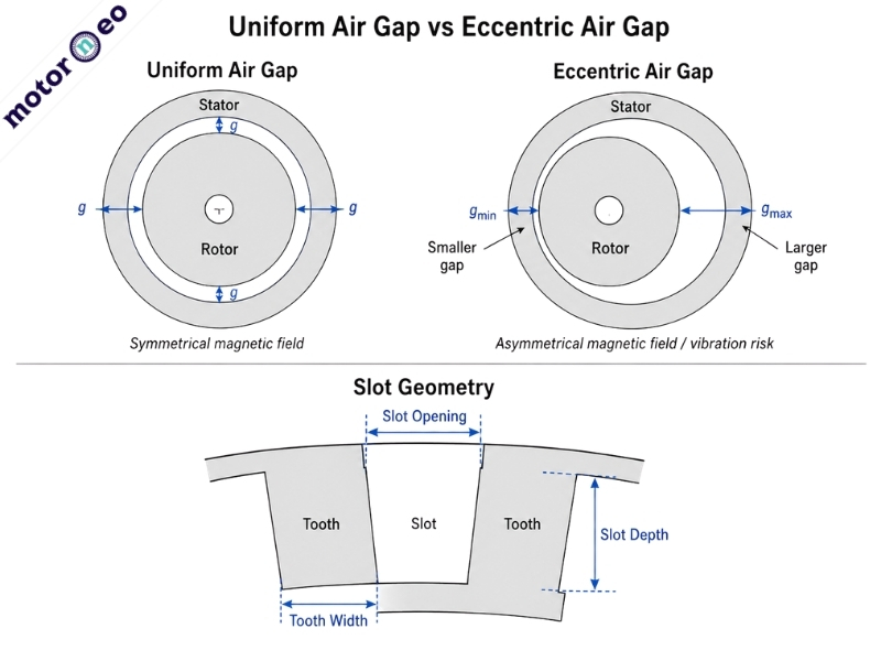
lot dimensions should not be overlooked either. If the slots are too small, the available winding space will be reduced. If the tooth width is too narrow, the local magnetic flux density may increase.
For multi-slot drone stators, if the slot openings, slot widths, or tooth widths are not consistent, the copper wire arrangement and local magnetic paths may also vary from slot to slot.
Therefore, for drone stators, dimensional tolerances are not only about whether the parts can be assembled properly—they are also part of the electromagnetic design.
Welding, Interlocking, and Bonding
Even well-made laminations can lose their material advantages during stacking. Poor stacking may damage interlaminar insulation, introduce stress, or reduce the stacking factor.
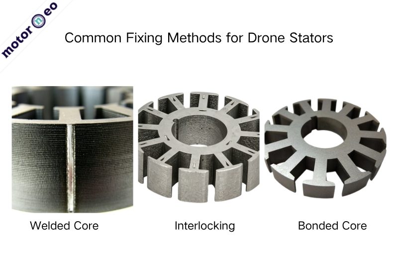
Common fixing methods for UAV stators include welding, interlocking, and bonding. All three can form a complete core, but they affect magnetic performance differently.
Welding
Welding provides strong fixation and uses a mature process. However, the weld area can create a heat-affected zone, local conductivity, and residual stress. Excessive heat input may also affect roundness.
Interlocking
Interlocking suits high-volume automated production. The laminations can be positioned and locked inside the die. However, the interlock points cause local plastic deformation. Their position, quantity, and size therefore require careful control.
Bonding
Bonding avoids obvious welding heat effects and does not require mechanical interlocks. It is common in prototypes and some high-performance projects. However, more adhesive is not always better. A thick adhesive layer increases the final stack height and reduces the effective steel ratio. In other words, it lowers the stacking factor.
This is why prototype and mass-production stages often use different solutions.
For small prototype quantities, laser cutting or wire EDM with bonding can work well. For volumes of tens of thousands, progressive dies, interlocking, production speed, and cost need to be reconsidered.
Which Core Problems Are Most Likely to Show Up in Motor Performance?
| Core Issue | Possible Effect | Impact on Efficiency |
| Burrs, interlaminar short circuits | Additional eddy currents, heating | Directly increases core loss |
| Punching stress | Reduced magnetic performance | Relatively direct increase in core loss |
| Stack height variation | Change in effective core length | Mainly affects motor parameters and consistency |
| Poor roundness or concentricity | Uneven air gap | Affects magnetic field, vibration, and efficiency |
| Slot dimension variation | Winding difficulty, changes in copper loss and flux density | May increase copper loss or local saturation |
| Improper welding/interlocking | Stress, local conductivity | May increase local core loss |
| Excessive adhesive thickness | Lower stacking factor | Reduces effective core utilization |
Core Efficiency Loss Can Start with the Very First Lamination.
“The drawing dimensions all meet the requirements. Why do two batches of motors still perform differently?”
The reason may lie beyond the drawing dimensions. Burrs and interlaminar short circuits can directly increase core loss. Punching stress can reduce local magnetic performance. Roundness and concentricity errors can disturb air-gap consistency. Poor stacking methods may also introduce stress or reduce the stacking factor.
These issues usually do not cause immediate motor failure. Instead, they gradually appear as higher no-load current, temperature rise, vibration, and lower efficiency.
Stable UAV motor efficiency requires more than 0.2 mm low-loss electrical steel.
If the motor already uses low-loss electrical steel but still misses its efficiency target, what would you check first? The material itself, or the finished stator core?